|
|
|
Basics of Modeling?
Believe it or not, we have now looked at all the tools we really need to build 9/10ths of all models. There are a few more special items we want to look at, but where polygon modeling is concerned, we have everything me need to make most shapes:
The most important thing you can learn at this point is that you can easily learn to create anything in 3D if you are determined to. Provided, of course, that you have good source material to start out with -- don't attempt to build any object without some sketches, photographs, etc. to guide you.
Just to keep life interesting, Iím building this model in Lightwave 3D 6.0. Iíll provide simultaneous instructions for how to do this in MAX, but Iím purposefully leaving out the minute parts of the instructions Ė we are not doing anything new in 3DS MAX here, so if this seems foreign, try repeating the pencil exercise (or earlier ones) until all of this seems easy. In other words, you'll have to do all the modeling yourself, I'm only providing a framework of methods to useÖ
You will need:
Letís try this out. Weíll begin by making a simple "free-form" vehicle, of no fixed design.
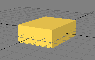
Draw a box shape like the one you see here, and:
In MAX, the subdivisions spinner is found in the object creation rollout or in the Modify rollout. Set each axis to "2".
Next, we will want to edit on a polygon level for this kind of modeling, so:
In Lightwave, press <spacebar> to toggle Polygon edit mode on (or click on the big "Polygon" button at the bottom of the screen).
In 3DS MAX, you will need to apply an "edit mesh" modifier, and open the sub-object area of the Modify Panel, and choose "polygon" or "face" drop down or button.
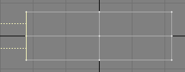 Now we want to select and edit the back part of the vehicle, as shown here. Notice the dotted yellow lines showing
 in this screen shot. These are the visible polygon "normals".
To see these in 3DS MAX, scroll to the bottom of the polygon or face sub-object rollout and place a check in the box next to "Show Normals" Ė then selected polygons will have visible normals (they are red or blue in MAX)
In Lightwave, the selected polygon count is shown at the bottom of the screen in a small field marked "Set". You should also evaluate the situation visually. Press "Shift <a>" to fit the four views to the selected polygons.
In MAX, I work by eyeball for this Ė examine the selection in all four views no matter which program you are using. Click on the "Zoom Extents Selected" gadget to fit the four views to the selected polygons.
Extrude the selected polygons, and move, rotate, and scale them as needed. Repeat as needed until the model is done!
In MAX, this is done with the "Extrude" and "Bevel" tools in the Sub-Object rollout. This is maybe a new feature to some people -- so there is one new thing -- try dragging the spinner for "extrude", and see what it does -- cool eh? You will also want to use the Move, Rotate, and Scale features found in the Main Toolbar to adjust each newly extruded segment.
In Lightwave, Use the "Smooth Shift" (Shift-<F>) and "Bevel" (<b>) features found in the "Multiply" Panel. Activate the tool, and then click and drag a bit on the selected faces Ė donít repeat this step unless you want to add more segments! Alternatively, you can select the tool, and press "n" to Activate and control it.
This a method commonly referred to as "box modeling". It is a useful method, not least because it allows you to create low-polygon characters with relative ease. You will find an enormous number of tutorials available to help with learning this method -- take the time to experiment and get comfortable,
and then try:
http://www.dlc.fi/~ops/tutorial/human.htmWhich is a link I got from
http://www.maxforums.org/tutorial.aspReady to experiment? Want to see a smoothed model?
In Lightwave, we can edit directly in "Sub-Patch Mode", which is something like "Nurbs", only different. Make sure nothing is selected, and press <TAB>. Press <TAB> again with nothing selected to return to polygon mode).
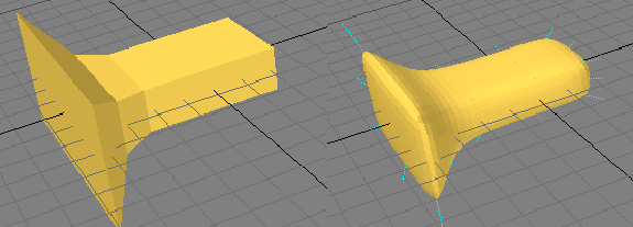
The object on the left is a "polygon" object. The one on the right is a sub patch object. Toggle between them with <TAB> (but make sure nothing is selected when you do so).
All tools and operations are the same in sub patch mode as they are in regular polygons mode, and you can switch between them at any time.
In 3DS MAX? The closest thing for this model is "Mesh Smooth" Ė it can be applied, and then you can return to the edit mesh level in the object stack to continue modeling. Remember to apply only one of each type of Modifier in MAX. To see the object in a smoothed state while you model, apply the MeshSmooth, pick "Edit Mesh" from the stack drop down, and click on the "test tube" icon.
I havenít used any other tools Ė and have in fact only done: select, smooth shift, move, rotate, scale, and repeat as needed. I have also renamed some polygons to new surface names and colors.
To be successful with this method, remember that what you have selected is vital to what will happen when you perform the extrude or smooth shift operation, and that you need to regularly adjust your viewports so you can see the selected part in all four views.
We'll look at this method of modeling more closely later on, but for now, experiment wildly -- make a dozen space ships, and then a dozen race cars. Throw them all away, and do it all again.
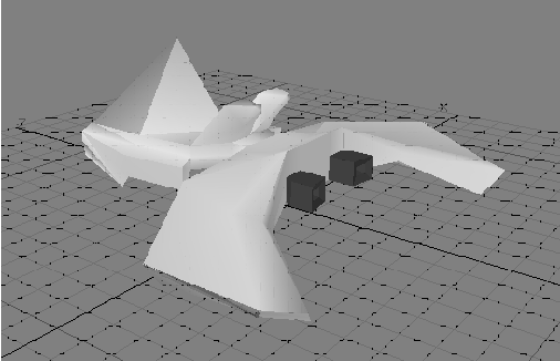 Above is the model before it is smoothed. This has less than 500 triangles. With adequate texturing, it can be made to look very nice however. This is a typical level of detail for a game object Ė it is a bit "heavy" for most VR applications. To make it simpler, I would leave off the sunken "insides" for the thruster holes, and leave off other detail you canít see in this shot, including a hatchway in the bottom which serves no purpose if we canít see it, and intake pipes on the front (also not visible in this shot).
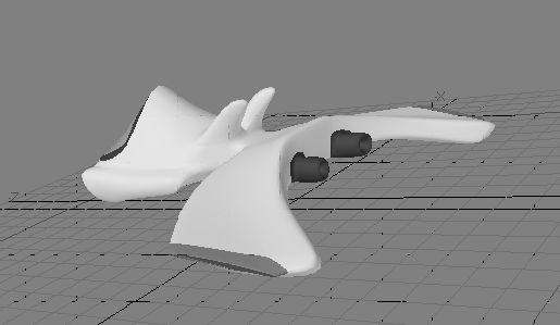 The second image shown is the same model with smoothing applied. Shown here, it consists of about 230 quadrangular "sub patches" with 5 real-time subdivisions each. If converted to polygons with the same apparent smoothness we see here, it would consist of 5800 quadrangular polygons, or 11,600 triangles.